// blog
How Four Views of a CT Stay Linked in a Browser Viewer (Developers)
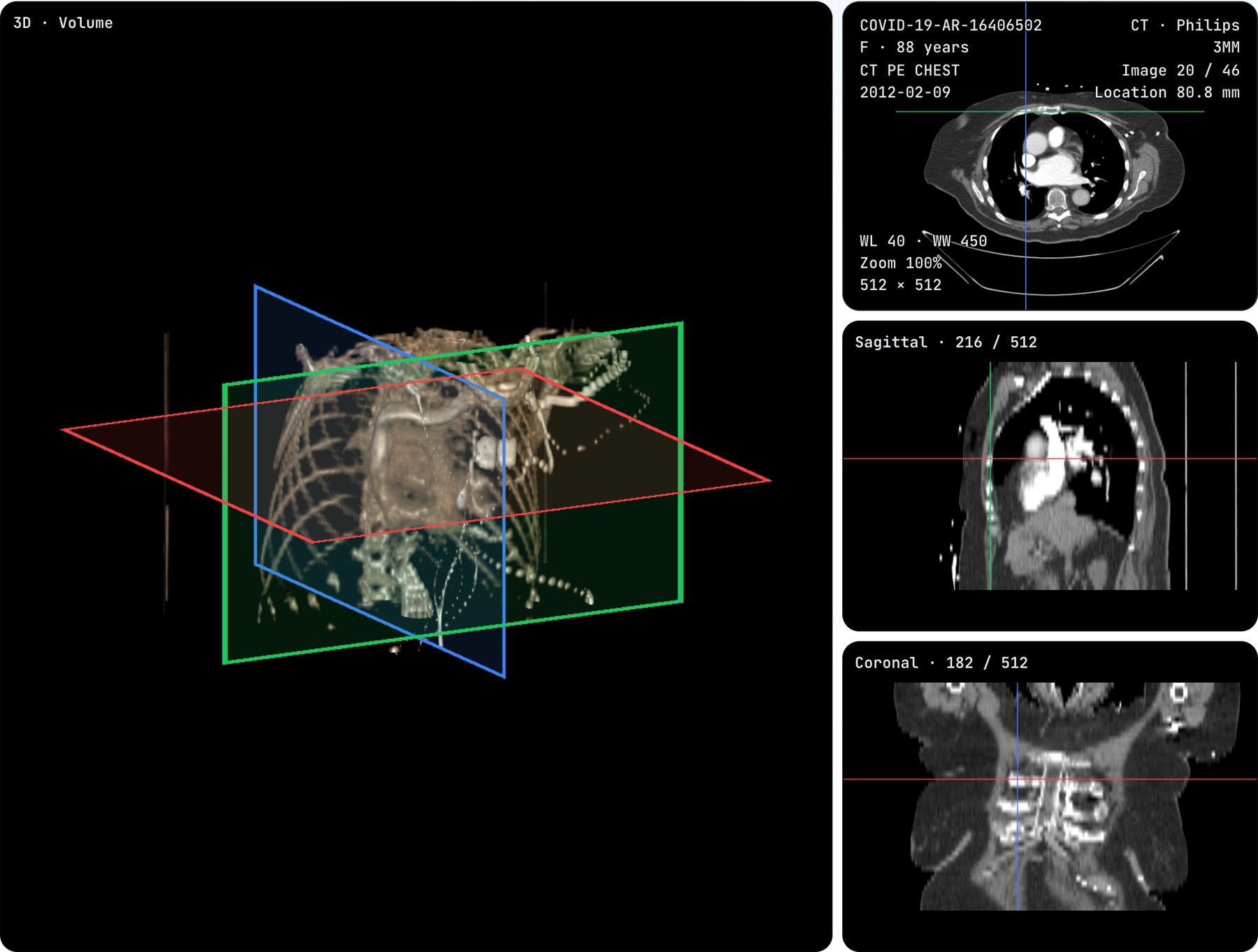
Our DICOM viewer links its four views through one shared point: a column, a row and an image, each from 0 to 1 in the data’s own order. Every view draws from that point and writes to it. The sagittal and coronal cuts are read straight from the decoded slices at full resolution; the 3D view outlines the three planes in its shader. A click in 3D runs the shader’s ray again in TypeScript: the first plane it meets in Planes, the brightest voxel in MIP, or where the look becomes half opaque in Volume. That voxel becomes the new point, and the other views follow.

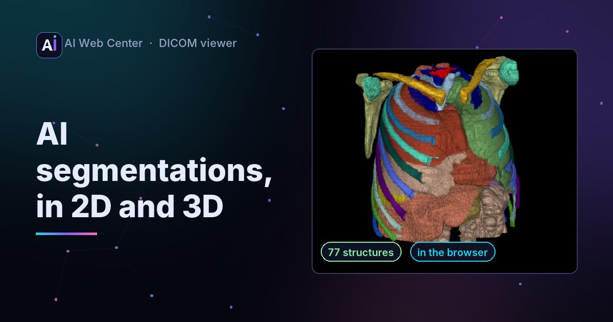
Our free DICOM viewer can now show a CT or MRI in four linked views: the slice, a sagittal cut, a coronal cut and a 3D view. Click in any of them and the other three follow. Here is how that works, with no imaging library: React, a 2D canvas and one WebGL2 shader.
One point, three numbers
Every view reads and writes one point:
// column, row, image: each 0 to 1, in the data's order (image 0 is the first in the series)
const pointAt: [number, number, number] = [planes[0], planes[1], (imageIndex + 0.5) / imageCount];
The slice shows image pointAt[2] with a crosshair at the column and row. The sagittal cut is the column pointAt[0], the coronal cut the row pointAt[1]. The 3D view outlines all three planes.
Fractions, not pixels, because each view has its own grid. The slices are 512 × 512, while the 3D texture is reduced to at most 256 a side so it fits any graphics card. A fraction means the same spot in all of them.
Cuts at full resolution
The first version read the cuts from the 3D texture: cheap, but blurry. Now they’re read from the decoded slices themselves. For a sagittal cut at column c, each image gives one row of the cut:
for (let z = 0; z < images; z++)
  for (let u = 0; u < rows; u++)
    cut[z * rows + u] = window((pixels[z][u * width + c] + offset) * slope + intercept);
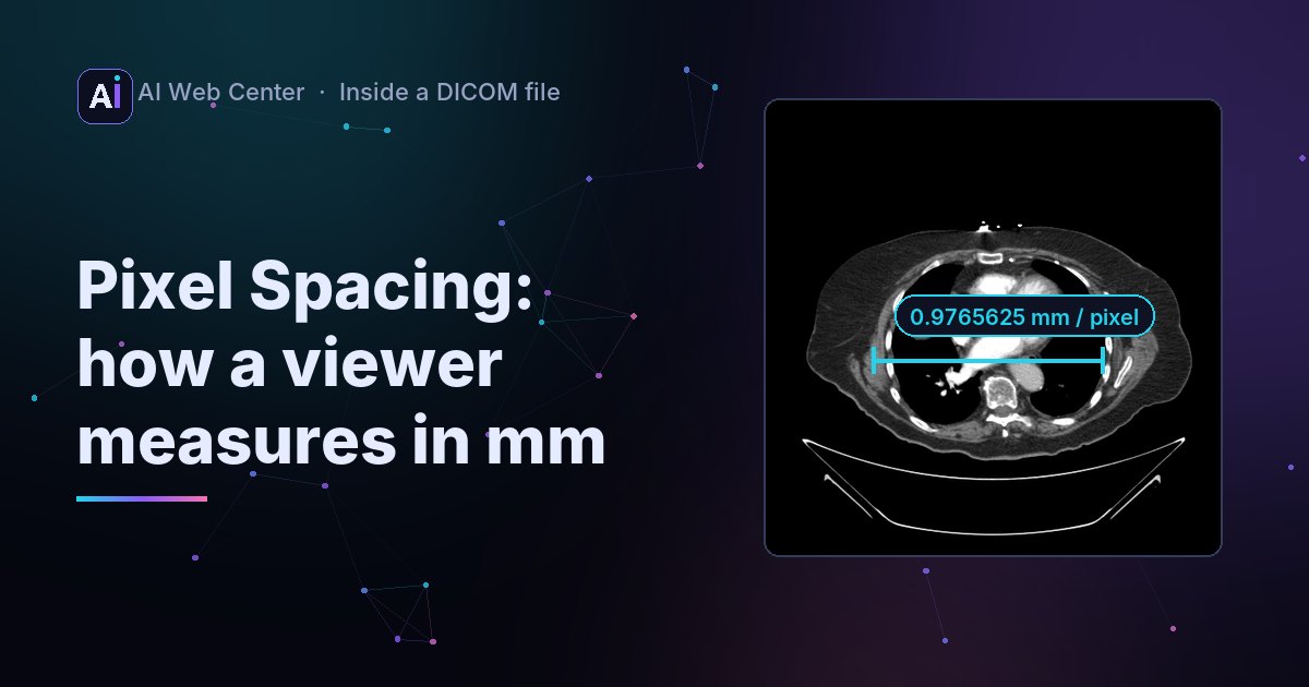
Each slice’s own rescale slope and intercept are applied, so the values are real Hounsfield units on a CT, then the window maps them to gray. The cut is drawn at its real size in millimeters: the pixel spacing across, the gap between images down. A 512-pixel row stays 512 pixels, and a series with 6 mm gaps looks stepped from the side, as it should.
The planes in 3D
The 3D view is a ray-casting fragment shader: every pixel sends a ray through the volume texture. To show where the other views are, the shader intersects the same ray with three planes and colours the pixels near each plane’s edge:
float t = (u_mark[k] * u_ext[k] - o[k]) / d[k];   // where the ray meets plane k
vec3 p = o + d * t;
vec3 e = abs(p) / u_ext; e[k] = 0.0;
if (max(e.x, max(e.y, e.z)) > 0.975) c.rgb = colours[k];   // its edge: an outline
Blue for sagittal, green for coronal, red for the slice, in every view, so the eye matches them without labels.
A click in 3D
The hard part is the click: which voxel did you mean in a volume render? The viewer runs the shader’s ray again in TypeScript, with the same camera, zoom, cut and look:
- Planes: the first of the three planes the ray meets.
- MIP: the brightest sample along the ray, the one the pixel shows.
- Volume: the point where the accumulated opacity passes one half, with the shader’s own opacity formula.
That point becomes the new pointAt, and React redraws the other three views. The tests check it on a made-up CT whose values rise image by image: from the top, MIP has to land on the last image, the brightest, and it still does with the volume turned upside down.
What we’d tell another team
- Keep one source of truth in the data’s order. Display turns (feet first, upside down) belong to the view that shows them.
- Don’t trust the GPU copy for 2D. It’s reduced to fit. Read cuts from the original pixels.
- Make the 3D click deterministic. No jitter in the CPU ray, or the same click lands on two slices.
Need imaging, or any heavy browser feature, built into your product? Tell me about it.
Frequently asked questions
Why not build the cuts from the 3D texture?
The 3D texture is reduced to fit any graphics card (at most 256 pixels a side and 512 slices). The cuts are read from the decoded slices instead, so they keep every pixel across.
How does a click in 3D find its spot?
The same ray as the shader, run again in TypeScript with the same camera, cut and look. Planes takes the first plane hit, MIP the brightest sample along the ray, and Volume the point where the accumulated opacity passes one half.
Why one point from 0 to 1?
Each view has its own resolution: the slices, the reduced 3D texture, the cuts. A fraction of the series works for all of them, so no view converts to another's pixels.
What about a series stored feet first?
The point is kept in the data's order. Only the 3D view turns it, when the volume is shown upside down, so the other views never need to know.